Mind Mirror EEG Contact Placement
All the early Mind Mirror research was carried out using a two channel EEG,
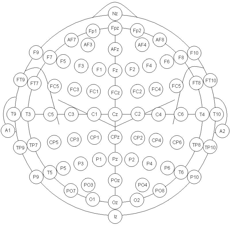
the Mind Mirror, with contacts placed over the occipital areas. Differential
pick-ups between contacts placed at T5 - O1 and T6 - O2 are used, rather
than the more usual common reference mode A1-A2. The rest of this monograph
will explain the reasons for these choices.
Common Reference pick-up (sometimes known as Monopolar pick-up)
A normal EEG reads voltages from many contacts and has a differential amplifiers
for each one. One side of each differential is connected to a common point.
This common reference electrode is usually created by joining the two ears
together A1-A2. The expectation is that the equivalent
point will appear to lie at the center of the head.
Differential Pick-up (sometimes known as Bipolar Pick-up)
As this requires two contacts at each pick-up point it is not practical for
normal EEG work which may require at least 19 channels. It has advantages when
only a few channels are needed.
All EEG amplifiers have amplifiers with differential inputs. Such amplifiers
respond only to the difference between the signals arriving at the two inputs,
if the same signal arrives at the two inputs it is cancelled out, a property
called common mode rejection. This enables the amplifier to reject unwanted
signals such as voltages external to the body caused by electrical power sockets
and lighting. Equally unwanted signals form inside the body such as those from
the powerful neck muscles or from the heart will be rejected. In either case
such signals contaminate the wanted EEG signal from the brain. The EEG signal
is quite large when measured on the surface of the brain but is severely attenuated
by the skull which, being
soaked in cortical fluid, is a very good conductor of electricity. Typically,
the voltage at the outside of the head may be as little as five millionths
of a volt. The ability to cancel unwanted signals is therefore a very important
property of an EEG amplifier.
Contacts T5-O1and T6-O2 are more or less equidistant from the powerful neck
muscles and from heart voltages and thus cancel these voltages more effectively
than the more normal common reference mode. Our experience suggests this is
especially advantageous in relation to eye muscle voltages.
EEG Rhythms
We do not know why the electrical activity of the brain takes the form of synchronized
activity which we call beta, alpha, theta and delta rhythms. One possible explanation
is that neurons join together in loops of activity (LA). Each neuron takes
a millisecond or less to respond. An electrical impulse from one neuron could
arrive back to it via a few hundred others linked together and so cause it
to fire again a tenth of a signal later. If this loop activity was repeated,
it could form the basis of the alpha wave These loops would lie along the brain
tissue and change direction along the folds of the tissue. Thus contacts placed
either differentially or in the more usual common mode arrangement would pick
up a similar signal. This is not an agreed theory but an attempt to explain
empirical measurements of EEG waves.
Another theory is that brain rhythms are generated by some kind of timing mechanism
in the central areas of the brain which cause the neurons of the cortex to
fire in regular patterns. If there was some kind of activity radiating outwards
from the center of the brain through the visual cortex, then signals picked
from T5 and O1 should be very similar and thus cancel out if applied to a differential
amplifier. We find this is not true.
Implementing a bilateral occipital hemispheric measurement with the 10-20 Electrode System
Using 3 electrodes of a standard system placed on T5 OZ and T6 a differential measurement of voltages can be found by then subtracting the signals T5-OZ, T6-OZ and then passing them through a band passfilters .